
(Louis Meulstee’s web site)
 Return
Electronic Fullerphone

Buzzer, Electronic, Fullerphone
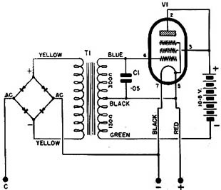
(i) The oscillator circuit in the Buzzer Electronic (comprising V1, T1 and C1) generated a signal of 600Hz. The output (1 volt AC) was taken from the secondary of the transformer and fed into the DC arms of the balanced bridge rectifier. The characteristics of the selected rectifier were such that equal current flowed through each leg of the bridge leaving no potential difference between the two AC arms. While the rectifier AC arms were thus balanced no tone would reach the headphones.
(ii) On receive a DC line current must pass through the rectifier bridge and through the winding of the induction coil. The AC flowing at 600Hz on this circuit created a varying load on the DC flowing in the Fullerphone circuit thus producing the signal in the headphones for the duration of the signal pulse.
(iii) On Send the closing of the make contacts of the key unbalanced the AC arms of the rectifier thus superposing the 600Hz tone upon the DC from the local X cell and was thus made audible in the headphones. The DC component was smoothed by the Fullerphone filter circuit and transmitted to the line in the normal way, the AC component being rejected by the Fullerphone circuit.
(iv) The valve plate supply of 10.5V enabled the buzzer to chop incoming line currents in excess of those normally used. The increase in output became proportionally less as the incoming current increased, and above 1.8uA input the output actually decreased a small amount. This characteristic gave an efficient crash limiting effect on momentary or transient currents which reached the buzzer.
In mid 1943 authority was given to the C.S.R.D.E. (Canadian Signals Research and Development Establishment) to start work on an electronic replacement for the mechanical Buzzer ‘F’ of the Fullerphone Mk.IV and Mk.V. In late 1943 CSRDE prototypes were available and January 1944 a prototype was examined at Northern Electric Co. which was also involved in the project.
In September 1944 the electronically-operated Fullerphone project was declared completed. An order was placed for 1000 Fullerphone Electronic Buzzers and 2000 batteries based on the replacement of each mechanical buzzer used in the Canadian Army plus 20% for spare and reserve, and in addition to one spare battery per buzzer.
In October 1944 three Canadian ‘Buzzer Electronic Fullerphone’ were tested by S.R.D.E. (Signals Research and Development Establishment) in the UK. They were considered as satisfactory in place of the Buzzer ‘F’ and suitable for tropical use, providing certain changes were made. The test report mentioned the disadvantages of the unit: slightly heavier than the Buzzer ‘F’ and requiring an appreciable higher current from the X cell which would have a life of 300 hours when used with the electronic unit as compared with several thousand hours with the Fullerphone Buzzer ‘F’. The merits were, however, no moving parts and contacts which made hand adjustments unnecessary, very little maintenance was required, crash limiting was an inherent characteristic, and it was silent in operation.
The Buzzer Electronic could be used in the Fullerphone Mk.IV, Mk.IV*, Mk.IV** or Mk.V in place of the Buzzer ‘F’ Mk.II, Mk.II* or Mk.II**. It slide into the same position in the Fullerphone as the Buzzer ‘F’. No mechanical or electrical modifications were needed to install this buzzer in a Fullerphone.
Mechanical construction.
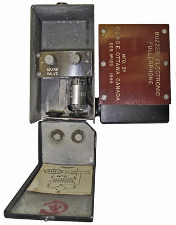
The electronic buzzer was housed in two cadmium plated steel compartments joined together to form one unit. The smaller of the two compartments (containing a copper oxide full wave rectifier, induction coil and capacitor) fitted into the buzzer housing of the Fullerphone. The three contacts were fastened on the base of this compartment.
The other compartment (containing one working and a spare valve type 1T4, and one 10.5V layer built long-life HT battery) rested on top of the Fullerphone case between the buzzer housing and the lid of the battery box.
The 1.5V LT supply was taken from the X cell already existing in the Fullerphone. The current drain from the X cell was 50mA, and 1mA was drawn from the 10.5V HT battery.
Circuit diagram of Canadian Buzzer Electronic which performed the same function as mechanical Buzzer ‘F’.

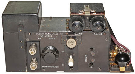
Fullerphone Mk.IV* with mechanical Buzzer ‘F’ (removable unit fitted on right hand top of the Fullerphone).
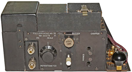
Fullerphone Mk.IV* with Canadian Buzzer Electronic sliding in the place previously taken by Buzzer ‘F’.
Working principle of the Buzzer Electronic.
Other photo awaiting.
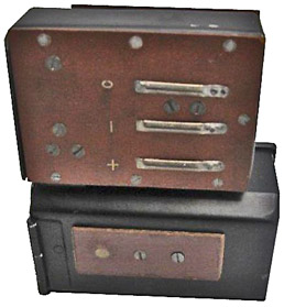
Top view of Canadian Electronic Buzzer with opened HT battery compartment.
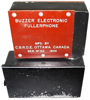
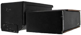
Front view of Buzzer Electronic with battery compartment closed.
Bottom view of Buzzer Electronic showing the three external contacts.
Top view of Canadian Buzzer Electronic.
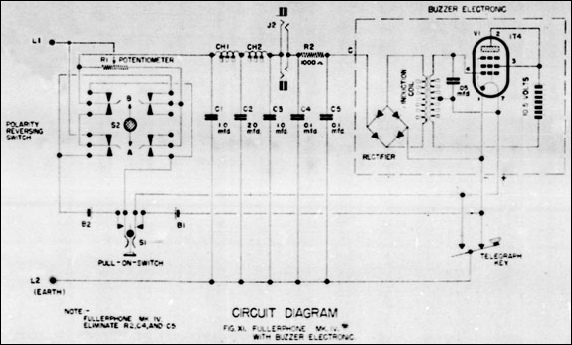
Circuit diagram of Fullerphone Mk. IV* with Buzzer Electronic. This diagram was taken from a microfilm and the represents the best what could be achieved.

